
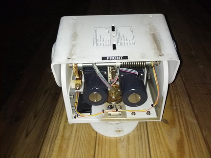
No, that isn’t a picture of a cute little robot. Or is it? It is a robot for moving your antenna but in a previous life it was a weatherproof mount for moving large expensive closed circuit TV cameras at secure facilities. With the cover removed, the motors look like eyes. Seller had 25 available and at least 11 have been sold but some are still available. New, it cost about $1000 or in the same price range as a Ham Alt/Az rotator but these are available surplus and in this case we have an unusually low price of $30 $39 on a Pelco, let alone one with the rare feedback pots, plus a reasonable price on shipping. I have purchased one and another club member has followed suit and a couple more plan to do so.
While these aren’t quite as good for amateur use as a proper az-el rotator, at least for large antennas, you will probably never get a deal anywhere near this sweet on one of those.
This article will describe these mounts in more detail and will also discuss how antenna rotators in general work, balancing and wind loading issues, and the history of stepper motors.
These mounts use worm gears. Worm gearing is a type of gearing in which a screw like helical “worm” mates with a gear with slanted teeth, the worm gear at right angles. These expensive gears offer high gear ratios with low speed/high torque outputs, resistance to back driving, low backlash, and often very high precision. They are commonly used in high precision applications like telescope drives and rotary tables on machine tools. This public domain animation from wikipedia shows a worm gear set in action:

The worm gears have approximately 60 teeth per revolution, so the output of the gear box is about 60RPM to achieve 6degree per second pan.
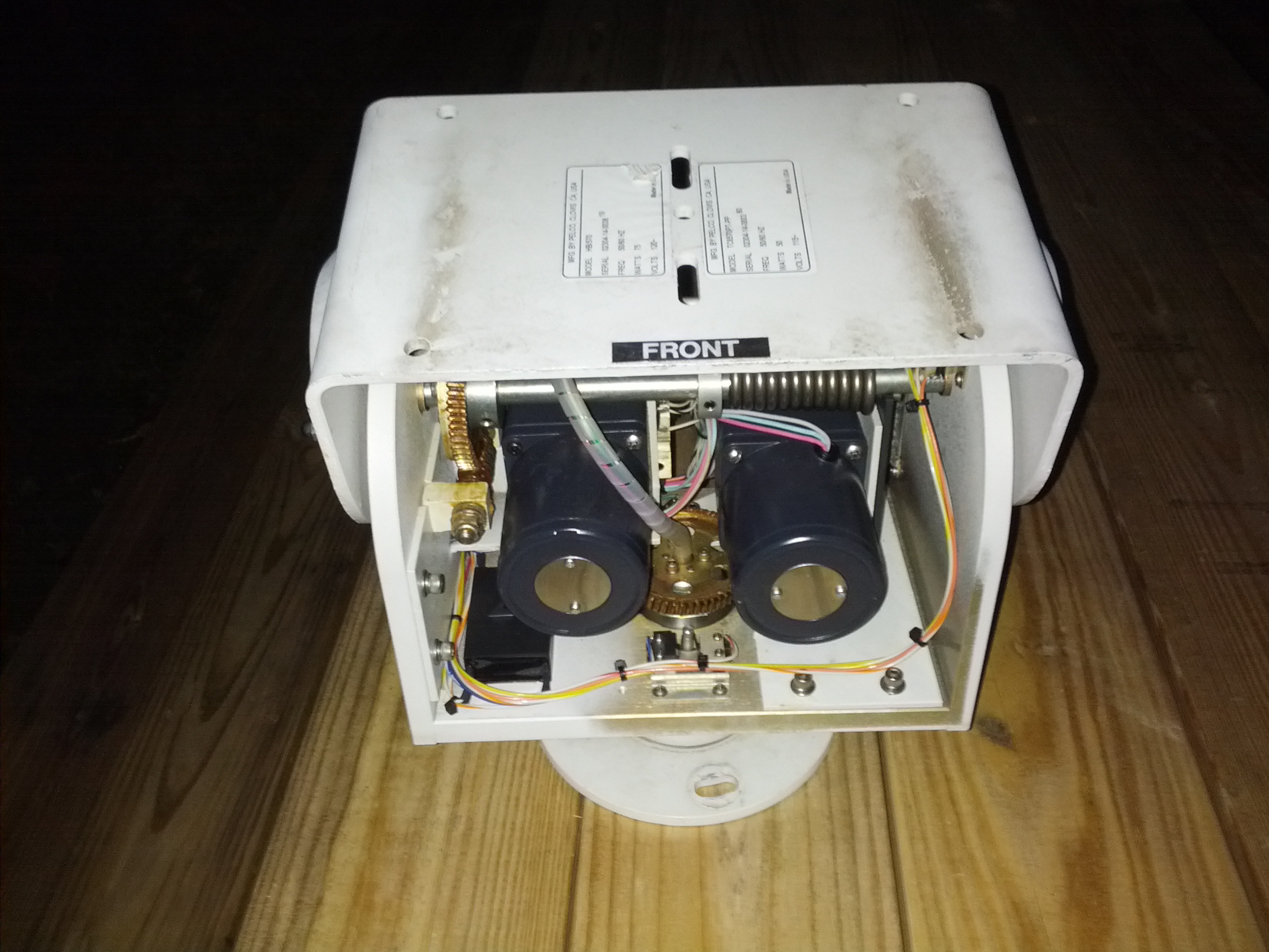
Picture of Pelco Pan/Tilt Mount with cover removed. Front Side. Visible items include two slow-syn synchornous AC motors in NEMA23 mount mounted on a gear box and two worm gear sets for vertical and horizontal rotation.
2592×1944 (5MP) Picture is scaled down to 640×480 (0.3MP). Right click and select view image on a typical browser for the opportunity to enlarge by clicking on image.
Picture of Pelco Pan/Tilt Mount with cover removed. Rear Side. Visible items include the feedback pots and gearing and the chain drive which connects the motor gear box to the worm.
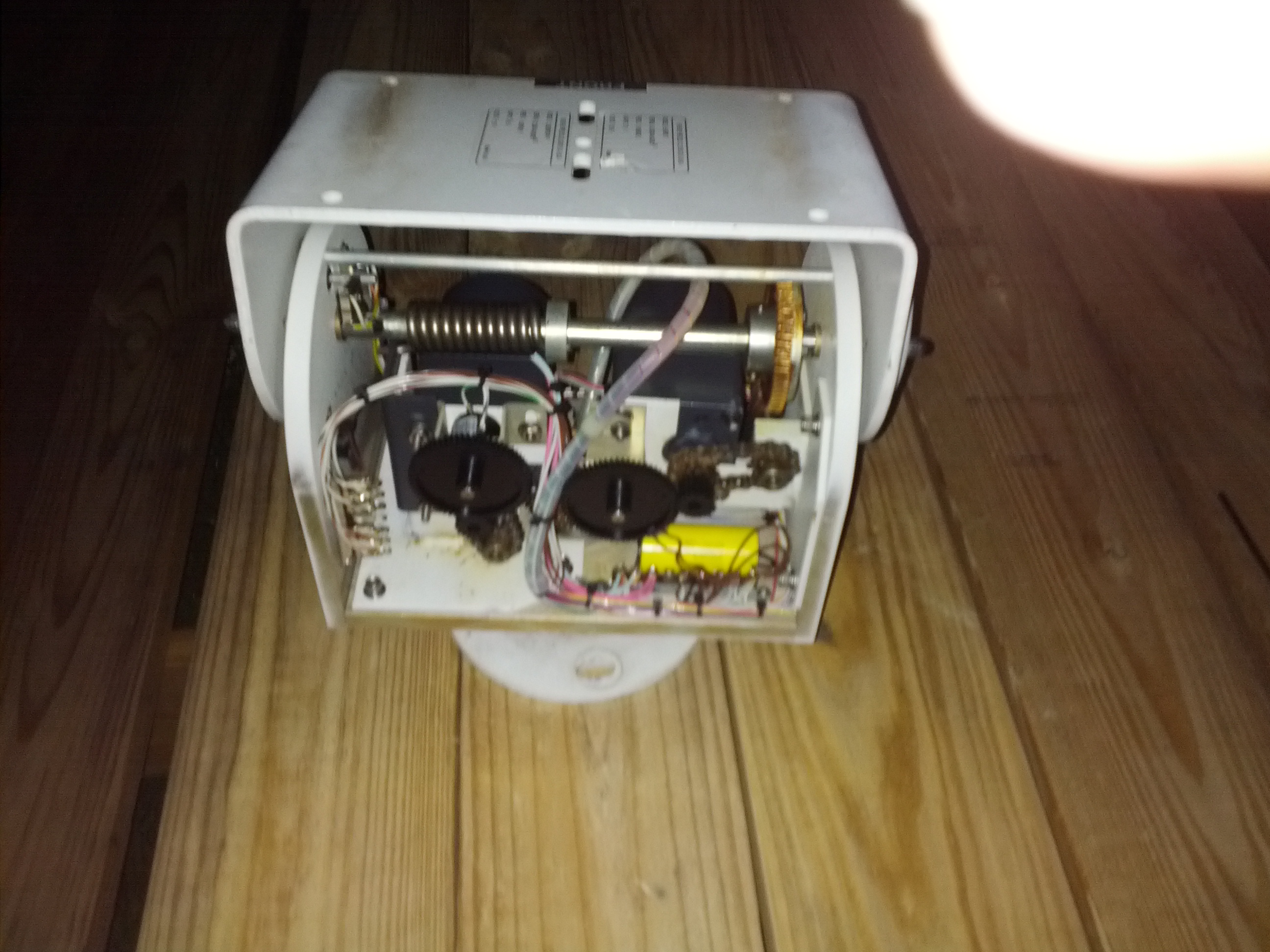
Scaled down image.
For those thinking about building their own satellite stations (kicksat and/or amsat), I recently purchased a Pelco TC6570PT-PP indoor/outdoor pan/tilt mount on Ebay. $30 + $13 ship (second unit ships for $3 more). These sell for about a grand new, today. There are about 20 more available, for those who are interested. These pan 355 degrees and tilt +/- 90. These are weatherpoof pan/tilt mounts made to run cameras up to 40lb. So they should be able to run an antenna or two if you keep the cantalevered weight and wind load down. 20 foot pounds elevation, 10lbs azimuth. Heavier if you balance it. By comparison, a Yeasu G-5500 can handle 101 foot*pounds in elevation and 44 foot*pounds in azimuth and costs $730; an external control connector is availible on the control box (for connecting to a $630 computer interface or $1360 total): it looks pretty similar to the pelco: 4 control contacts and 2 pot outputs except the relays are in the G-5500 control box. As far as static weight: I have personally stood on the pelco. It didn’t notice. But don’t try that when it is bent over looking at its toes.
I have used similar borrowed unit, but not this exact model before, under open loop computer control; well, not exactly open loop – a TV camera completed the loop with a computer analyzing the TV video. The -PP on the part number indicates that it has feedback pots on pan and tilt. These pots connect to a 5V supply (3.3V or 2.5V would also work) and provide a 0-5V (or other supply voltage) output based on position. These particular units also have a small 75 Watt HB/570 heater installed inside for use in very cold weather. Without heater: -23 ℃ (-℉), with heater I think it is god to.-50 ℃ (-48℉), Charlottesville record low -10℉. It is rare to see these units this cheap, let alone with the rare feedback pots (the “PP” = Preset Position in the part number) and heater.
Listing I bought: http://www.ebay.com/itm/Motorized-Pan-Tilt-Heads-Pelco-Philips-/390705318715
relisted: http://www.ebay.com/itm/Motorized-Pan-Tilt-Heads-Pelco-Philips-/390712075756
relisted again: http://www.ebay.com/itm/Motorized-Pan-Tilt-Heads-Pelco-Philips-/390719241589?
Datasheet:
http://www.sourcesecurity.com/docs/fullspec/TC6570.pdf
Manual for a different model that shows wiring:
http://rikain.com/Manuals/CCTV_Closed_Circuit_Television/Pelco/Pelco_PT550P_Series_PT570_Series_PT573_Series_PT680-24_Series_Medium_Duty_Pan_Tilt_service_manual.pdf
Note that this is the unit available is a …6570… rather than …570… but they seem pretty similar. The “6” probably gets you a “Philips” nameplate on each side or some other minor modification. It is the PT570P/PP model that is currently selling for $913 to $1053 and the blanket heater adds about $215
Note that the price and shipping has gone up a bit and that the best deal on shipping is to purchase in multiples of 3 rather than 2. Price including shipping is $56 for one, $52 each if you order two, or $50 if you order 3 and jumps back up to about $53 each if you buy 4-6.
I suspect the wiring is similar to Figure 10 and the mechanism similar to Figure 1.
These units have 117VAC Gear motors driving expensive worm gears that pan the unit at about 6 degrees per second or tilt at 3°/S. You need 4 relays connected to a ULN2003, ULN2803, or discrete bipolar transistors or mosfets (don’t forget the back diode) drivers to connect to the GPIO port on a microcontroller or PC parallel port. You pulse these briefly to move in small increments. One cycle of AC, 1/60th of a second, or 16.7ms would in theory move 1/10th of a degree.
– Raspberry PI with AC adapter
– Ethernet runs to computer
– USB connects to RTL-SDR, runs rtl_tcp to act as SDR server.
– GPIO connects to A/D board
– GPIO connects to relay driver
– ADC board
http://www.adafruit.com/products/1083
http://www.adafruit.com/products/1085
adafruit also sells a MCP3008 8 channel 10 bit ADC chip but 10 bits is a bit anemic.
– Prototyping board for relay driver, one option is
http://www.adafruit.com/products/801
but not a lot of room for relays.
– optional: additional relay for heater and temperature sensor (should already have a built in thermostat).
– optional: phase reversal RF relay for changing right/left or horizontal/vertical antenna polarization.
– optional: internal/external RF switch (relay) for using antenna with other than rtl-sdr; i.e. a transmitter.
– Optional: AMP CPC 16 pin plug housing (size 17 shell???) $5, contacts about $0.50 each, plus waterproof hood and cable clamp. Mouser.
http://www.mouser.com/catalog/catalogusd/646/1576.pdf
Connector shell: http://www.mouser.com/access/?pn=571-2060371 $4.95
contacts (gold, 20-24AWG): http://www.mouser.com/access/?pn=571-665654 $0.49*16
Peripheral Seal: http://www.mouser.com/access/?pn=571-2064032 $0.77 (gasket)
Unsealed Boot: http://www.mouser.com/access/?pn=571-206070-8 $3.68, not weather sealed
Sealed boot: http://www.mouser.com/access/?pn=571-54011-1, $16.78, heat shrink
Unsealed total: $17.24 (Need to use external sealing wrap.
Sealed total: 30.34
Accessory catalog page: http://www.mouser.com/catalog/catalogusd/646/1579.pdf
Manufacturer CPC connector series catalog Sections 1-5 and sections 6-9
One option would be to build all the electronics inside the pan/tilt enclosure. It is a fairly large box, weatherproof, with heater. Need waterproof or weatherproof connectors or glands for the ethernet and 117VAC power connections. Note that there is not a lot of space inside that isn’t used by the mechanics.
Those who wish to could replace the AC motors with stepper motors (possibly leaving the gearhead), though this is more involved.
Note that the AC motors inside, separate from the gearboxes, look like they may be NEMA 23 frame size – the same size used by many stepper motors and indeed, they may be the 115VAC equivalent two phase motors, similar to a Slo-Syn motor. These motors would be run with one phase directly on 115VAC and the other phase connected to 115VAC through a capacitor. With one wire of each phase connected to common (neutral) and the capacitor connected between the other connections on each phase, then depending on which phase you connect AC to, the other phase is fed through the cap and the motor direction changes.
Note that since these are apparently synchronous motors, you can more or less run them open loop and compute the position based on time, though you will have to recalibrate periodically by driving into the limit switches. This is the approach used by most cheap TV antenna rotators today. You can also make indicators using the shadow motor technique used in some TV antenna rotators, though in this case you can use a meter movement and have absolute accuracy.
Although stepper motors date back to the 19th century, it wasn’t until the 1957 that the permanet magnet version was developed by GE and entered production. But it is the 1960s stepper version of the slo-syn motor (1958) that seems to have largely popularized their use. The slow syn motor was a 2 phase AC motor with an unusually high number of poles with 24 to 200 poles such that it takes 6 to 50 electrical revolutions to make one mechanical shaft rotation. Rewind these motors for lower voltage use and you have a stepper motor. Many of the old stepper motors I have encountered slow-syn steppers. Stepper motors are widely used in applications such as computer printers, floppy disk drives, early consumer hard drives, robotics, pan/tilt IP cameras, and CNC machine tools. Slo-syn museum.
Those who want less complexity can give up computer control and automatic tracking but still come in out of the cold (kicksat launch is in february) or avoid hand fatigue. 2 SPDT center off toggle switches (plus SPST for heater) or a 4 switch joystick will run the pan/tilt and two meter movements calibrated to 5V and a 5V cell phone (usb or surplus cell phone) power supply will display position. Add wire and connector. Here is a 5V analog panel meter for about $4 on ebay. Presumably, you can take it apart and print up a new faceplate.
Note that this pan/tilt does not rotate the antenna about its axis for polarization changes and should be used with a circularly polarized or switchable antenna or a rotator.
A possible alternative is to run two rtl-sdr receivers, one each horizontal and vertical, and when one fades the other will hopefully be strong. Run two decoders. Here is an article on partially synchronizing the clocks:
http://kaira.sgo.fi/2013/09/16-dual-channel-coherent-digital.html
Polarization switching using relays:
http://www.pa3guo.com/polarizer.html
http://www.sm5bsz.com/polarity/simplesw.htm
Wind load:
http://www.amsat.org/amsat/archive/amsat-bb/200105/msg00815.html
Worst case wind load, 30inch diameter (15inch radius) satellite internet dish in 100mph wind (hurricane shelters designed for 240mph).
$ units -1 -v “0.5*1.2kg/m^3*(100mph)^2*1.2*pi*(15inch)^2″ kg*force
0.5*1.2kg/m^3*(100mph)^2*1.2*pi*(15inch)^2 = 66.912062 kg*force
Also, 52mph and 240mph:
0.5*1.2kg/m^3*(52mph)^2*1.2*pi*(15inch)^2 = 18.093022 kg*force
0.5*1.2kg/m^3*(240mph)^2*1.2*pi*(15inch)^2 = 385.41348 kg*force
Of course, you would need to mount the dish rather oddly to get that amount of force tangent to the rotation. A winegard dish is rated for 50mph operate and 100mph withstand.
0.5*1.2kg/m^3*(50mph)^2*1.2*pi*(15inch)^2 = 36.878961 pound*force
0.5*1.2kg/m^3*(100mph)^2*1.2*pi*(15inch)^2 = 147.51585 pound*force
Here is a link to a picture of a pelco supporting a satellite/microwave link dish. Note that this is a bad way to mount it unless you need to aim below the horizon (which they may need to do) but they use a open mesh dish which lowers wind loading. For satellite use, just mount the back of the dish flat on the yoke.
http://www.sbe24.org/techdocs/geosat/pelco.asp
Unbalanced 10 element 70cm yagi on 1″ round boom, 4ft long, center of force cantelievered 2ft 5inch from pan-tilt axis can move stand up to about 54mph (pan) and 74mph (tilt) while operating against the wind:
0.5*1.2kg/m^3*(54mph)^2*1.0*(48inch*1inch+10*0.25inch*70cm/2)*(2ft+5inch) = 10.104475 foot*pound*force
0.5*1.2kg/m^3*(76mph)^2*1.0*(48inch*1inch+10*0.25inch*70cm/2)*(2ft+5inch) = 20.014899 foot*pound*force
I estimate that you would strip a tooth off the worm gear at around 500inch pounds, assuming single tooth loading and tooth dimension of about 0.25inch by 0.125inch and sheer strength (brass) of 34100psi and a 2inch gear diameter (1inch radius). This is just a rough estimate; I have not measured these
34100psi*0.125inch*0.25inch/force = 483lbs.
This would correspond to about a 100lbs camera weight at 5″ offset. Heavy HF beam antennas or moonbounce arrays would, therefore, need counterweighting on the opposite side of the tilt axis. This is an advantage to a true az-el rotator in that it is designed for concentric rather than offset mounting.
Pelco mounts are available in larger, heavier duty sizes, in explosion proof versions, and in radiation hardened versions, and with RS-485 control. . Here is an example of some pan/tilt units with built in RS-485 and higher wind loads:
http://www.2bsecurity.com/pan-tilt-heads.html
There is an RS-485 controller board on ebay:
http://www.ebay.com/itm/RS485-Decoder-Board-for-CCTV-Security-Camera-PTZ-Control-PELCO-/390705841679
http://www.best-china-security-supplies.com/download/ug_sy820q.pdf
However, while this has relays to control up/down/left/right, it does not handle the feedback pots.
Control for a single axis rotator I was looking at, shows triac circuit option instead of relays, gives schematic of rotator.
http://www.aprs.org/rotator1.html
I was looking at this device for polarization. Seems a little slow. These, like many other tv antenna rotators, operate quasi-synchronously. This would probably be similar in design (AntennaCraft TDP-2 at solidsignal.com cyber sunday $45+9.95 ship):
http://www.solidsignal.com/pview.asp?p=tdp2&d=antennacraft-by-radioshack-tdp2-tv/fm-tv-antenna-rotator-%28tdp-2%29&sku=4029340007
The newer ones with a digital display, such as RCA VH126N, work on the same principle: timing.
voxxintlcorp.com/docs/common/VH126N/VH126N_OM.pdf‎
As far as physically running the rotator, they work very similarly to the pelco and could be controlled with a toggle switch.
A combination of eggbeater and IOio antenna design is an option (no rotator):
http://personales.ya.com/ea4cax/paginaea4cyq/Antenaioio/ioioingles.pdf
http://wb5rmg.somenet.net/k5oe/Eggbeater_2.html
Note that the modified eggbeater works without tracking for amsats.
PELCO PM2000 is a 24″ pedastal (~$70) on which the rotator can mount and PM2010 is the shorter version. There are also wall and parapet mounts. But the flange for a 2” Class 150 pipe has the same bolt circle. $6.29 at zoro tools.
http://www.zorotools.com/g/00023180/
Control methods overview:
- Open loop, 4 switch contacts
- 4 switch contacts, meter feedback. Human closes the loop.
- open loop with simulated feedback in the form of synchronous motors driving an indicator
- Same as above but with microprocessor timing. Moves are fairly accurate if not stalled but there is some uncertainty that creeps in at the begining/end of a move which can accumulate.
- Closed loop control: 4 relays, microcontroler, A/D converter with pot feeback
- replace motors with stepper motors, with or without microstepping, with or without pot feedback. Computer controlled. Open loop but not an issue unless you stall the motors.
- Original motors, treated as high voltage stepper motors using an inverter.
- Original motors, driven with low voltage, low frequency, normal current levels, as microsteppers. Similar in some respects to a variable frequency drive. Due to low voltage and inductance limiting frequency, instead of taking up to a minute to acquire target, it could take up to 10 minutes.
NEMA 23 size stepper motors area available for around $15. Get ones capable of unipolar operation (6/8 lead vs 4 lead) if you want to be able to use a more primitive drive.
16 conductor cable from mouser would be $139/100ft. However, two lengths of 8 conductor CAT5 would do the job. Get 24AWG instead of 26AWG and copper instead of CCA (copper coated aluminum). About $16/100ft or $32/100ft doubled up. Two jackets is a little more difficult to seal than one jacket and you have two cables to run instead of one. And you might be putting your micro-controller close to the pan/tilt, anyway.
Cheapo 5V coil SPDT 3A relays, $4.10/5 from Deal Extreme:
http://dx.com/p/hk4100f-dc5v-shg-6-pin-power-relays-yellow-5-piece-136788
http://www.ever-way.biz/uploads/soft/110512/HK4100F.pdf
Name brand, larger, 10A SPDT from mouser:
http://www.mouser.com/ProductDetail/Omron-Electronics/G5LA-14-CF-DC5/?qs=sGAEpiMZZMtGt%252bn33CgIP9KQxQ3AI1MN8zjPifxkSlg%3d
Or in between size 5A SPDT from mouser:
http://www.mouser.com/ProductDetail/TE-Connectivity-OEG/9-1440003-7/?qs=sGAEpiMZZMtGt%252bn33CgIP1w90c6y9fzNKAHPzdLAv4I%3d
Relay life may be rather limited, since a typical rating would be 100,000 cycles. However, running at 1/10th rated current, this increases to a million cycles. But frequent tweeking of position or hunting by computer can use this up very quickly. Tracking 3 objects per night 120 degree across the sky in 0.1 degree increments is 3600 operations/day and 1million operations/9months. 1 degree minimum movements would extend life and result in much less accumulated error.
Triacs may be used with an isolated triac driver such as this:
http://www.fairchildsemi.com/ds/FO/FOD4216.pdf
Or use a solid state relay such as this $5 8A one from spark fun:
https://www.sparkfun.com/products/10636
Other uses for the pan tilt mounts include as a solar tracker (be careful of wind loads).
If you buy one of the pelco mounts, let me know. We might be organizing a group buy on the mating connector.
Note that the price and shipping has gone up a bit and that the best deal on shipping is now to purchase in multiples of 3 rather than 2. Price including shipping is $56 for one, $52 each if you order two, or $50 if you order 3 and jumps back up to about $53 each if you buy 4-6.